V-diagram
The most simplified, popular, and widespread visual representation of the "single" life cycle with the demonstration of key practices in their deployment over "logical time" is the V-diagram (V-diagram, Vee diagram), popularized in 1991 by Kevin Forsberg[1]:
It is a "cultural heritage" from past times, and it is necessary to know it at least to be able to engage in a conversation with engineers from older generations.
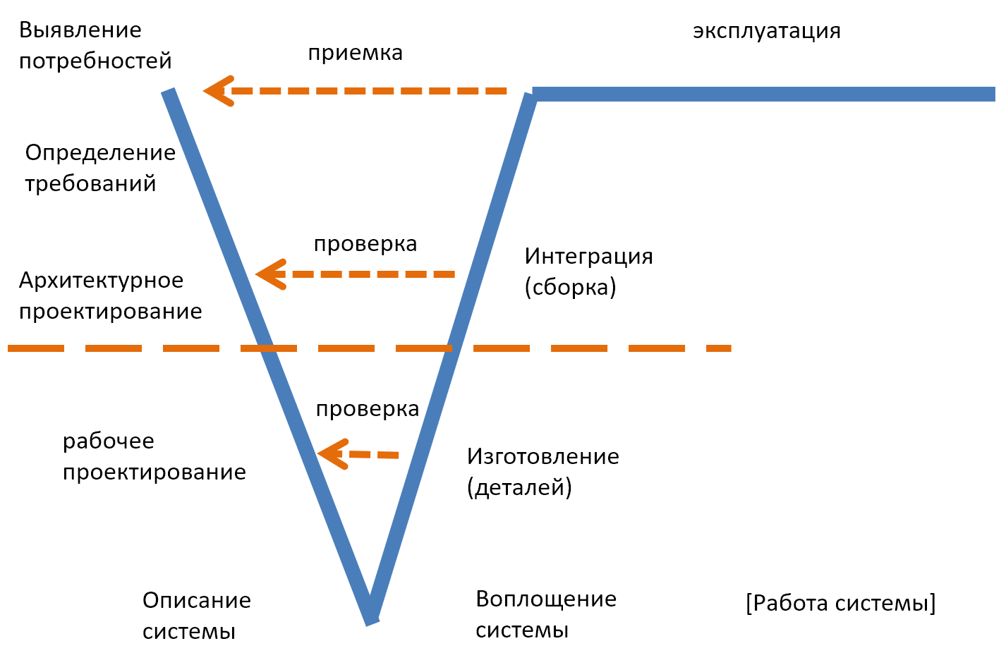
The name of this diagram comes from the shape of the Latin letter V, and the form represents the timeline, bent in half at the point where the elaborated stage of system description/system definition transitions to the elaborated stage of system realization. So, it is a two-dimensional diagram: stages (activities unfolding along an implicit timeline) are represented horizontally, and practices are indicated vertically in different parts of the diagram. This diagram also reflects the old-fashioned view of development practices: not so much the formulation of hypotheses about what the usage concept might be, but the "identification of needs" and "definition of requirements" (requirements definition). We will not update the set of practices to modern ones on this diagram; we present it in a way familiar to the previous generation of engineering.
The bend in the timeline is easy to understand if you remember that in functional diagrams, time is "logical," as these are not steps of work carried out sequentially, but practices/functions. Therefore, on these "non-sausage-like" life cycle diagrams with a methodology oriented towards practices, not just stages, time indicates not necessarily a strict order of work execution but the activities/practices that need to be undertaken in the project. Nevertheless, on this diagram, three "logical" stages of conditional work can be distinguished (or "elaborated practices, work performed sequentially"), in which the "waterfall" is clearly visible.
The first of them is the system description stage (system definition, design), when the physical system/realization of the system does not exist, and the primary practices are engineering requirements, system architecture engineering (in its old understanding), and (working, that is, with accuracy sufficient for manufacturing) design. This is "bit work," informational. The term "system description" is thus used in two different senses (and never in the sense of the "textbook definition" from an incorrect translation of system definition!), and its meaning is determined by the context:
- Information about the system, expressed in requirements, architecture, and the non-architectural part of the project/design (emphasis on the fact that this description is like the content of the system documentation)
- A generalized/elaborated stage of the life cycle, that is, work on describing the system/creating a system description in the first sense of the word (information about the system, not the stage).
Next, the timeline makes a bend, and logically begins the second stage of system realization (realization as "bringing into reality"). The term "system realization" is also used in two literal meanings:
- The name of the type of the system itself as a physical entity in space-time
- The name of the generalized/elaborated stage of the life cycle, in which various practices work on realizing the system in the physical world (not description work, not operational work).
The V is required to show the engineering assurance. These assurances are divided into two types: verification and validation. The manufacturing of system details (subsequently indivisible modules in the project) is done and checked in accordance with the project/design, and the verification arrows demonstrate this fact. For the display of these realization correspondence checks, the V-diagram itself is made: it shows a way of working/life cycle view/ordered logical set of practices in which the realization/creation/system realization occurs not by trial and error in the physical world but first through reflection and modeling-documentation/system description. And the created/realized (manufactured in the form of details, and then assembled from these details) system is tested for its compliance with its previously developed description—these checks are represented by verification arrows on the diagram.
The last thing that happens during realization is the system handover/validation, which takes place in the form of conducting tests to meet the requirements defined at the very beginning (that is, it is checked that it is happening not with the target system but with the supra system, when the target system is operational within it—the supra system is tested, or at least its model/emulation/imitation).
On V-diagrams, the stage of dismantling from operation has not yet been depicted. This reflects the gradual perception of system thinking by engineers: first, the idea of the project development life cycle (what system engineers are involved in in their project), then the coverage of the operational stage by thinking (another step towards maintaining focus on the complete life cycle), and only in recent times (already in the 21st century, starting with the ISO 15288 standard, the first version of which was released in 2002), the omission is the mandatory consideration of the complete life cycle—including the (investment, commercial) concept, starting from checking the project idea's compliance with the enterprise strategy taking over the project, and ending with decommissioning/destruction after use.
The horizontal dashed line separating the top and bottom of the V-diagram is often used to separate the practices and work (in the V-diagram, practices and work are intertwined and not clearly separated) of system engineering (that is, practices and work with requirements, architecture, verification, and validation) from the practices and work of subject/applied engineering, that is, from the practices and work on the working (not architectural: in working design, the necessary detail for manufacturing, not just the most important aspect, as in architectural) design of mechanical, electrical elements, software coding, and then manufacturing/realization of mechanical and electrical parts of the system, deployment of software parts of the system on target computers. Therefore, the diagram shows that system engineering practices are mainly encountered at the initial and final stages of the project, and in the middle of the project, the work of various other engineering specialties predominates, directed by a few architectural solutions.
The V-diagram is one of the first (it's 1991, the spiral diagram is 1986, practically indistinguishable in historical terms) "logical" diagrams, "principal life cycle schemes," where activity practices named after substantive engineering disciplines appear. Its main innovation is the separation of practices for describing and realizing the system with checks and acceptances of their mutual correspondence, not just the interest and resource-requiring work of life cycle stages with a rough separation into conception, development, manufacturing. The V-diagram largely retains the characteristics of the waterfall life cycle, but the transition to a two-dimensional representation of the life cycle from the "sausage" already provides much—there are a huge number of variations of the V-diagram discussing different aspects of architectural decisions on the life cycle: how practices are involved in works[2].
The V-diagram, preserving at least the appearance of the waterfall sequence of practice application, depicting "continuous progress" without returns and repetitions, was not as radical as the spiral depiction of the life cycle, so it became popular with managers and gained immense popularity. The V-diagram is actively used today.
Forsberg, K., Mooz, H., 1991, "The Relationship of System Engineering to the Project Cycle", Chattanooga, Tennessee: Proceedings of the National Council for Systems Engineering (NCOSE) Conference, pp. 57-65., http://www.damiantgordon.com/Courses/ISE/Papers/The%20Relationship%20of%20System%20Engineering%20to%20the%20Project%20Cycle.pdf ↩︎